The MX960 platform is known as one of Juniper’s flagship platforms in that it is flexible enough for deployments across services providers and enterprises alike. Recently I had the experience of converting an MX960 Virtual Chassis (VC) to an MX960 Multi-Chassis Link Aggregation Group (MC-LAG). This post discusses how the migration was performed.
Before I begin diving into the actual migration we need to first understand the MC-LAG configuration on the MX’s. I chose to utilize an Active/Active topology with MAC Synchronization for Layer 3 routing for this deployment because we had the correct hardware components and JUNOS software. The Juniper MX Series book available on O’Reilly is an excellent resource to understand the requirements, configuration, and maintenance of the MC-LAG as well as an overall resource for the MX Series. I cannot recommend it enough!
In an Active/Active MC-LAG topology the MX MC-LAG configuration requires a link for the Inter-Chassis Control Protocol (ICCP), the Inter-Chassis Link (ICL), and the LAG configuration.
The ICCP configuration is straightforward; configure the ICCP protocol and switch options:
MX-01:
interfaces {
    ge-0/1/1 {
        gigether-options {
            802.3ad ae20;
        }
    }
    ge-0/1/2 {
        gigether-options {
            802.3ad ae20;
        }
    }
    ge-0/2/1 {
        gigether-options {
            802.3ad ae20;
        }
    }
    ge-0/2/2 {
        gigether-options {
            802.3ad ae20;
        }
    }
    ae20 {
        aggregated-ether-options {
            lacp {
                active;
                periodic fast;
            }
        }
        unit 0 {
            family inet {
                address 10.19.211.1/30;
            }
        }
    }
}
protocols {
    iccp {
        local-ip-addr 10.19.211.1;
        peer 10.19.211.2 {
            redundancy-group-id-list 1;
            liveness-detection {
                minimum-interval 150;
                minimum-receive-interval 60;
                multiplier 3;
            }
        }
    }
}
switch-options {
    service-id 1;
}
MX-02:
interfaces {
    ge-0/1/1 {
        gigether-options {
            802.3ad ae20;
        }
    }
    ge-0/1/2 {
        gigether-options {
            802.3ad ae20;
        }
    }
    ge-0/2/1 {
        gigether-options {
            802.3ad ae20;
        }
    }
    ge-0/2/2 {
        gigether-options {
            802.3ad ae20;
        }
    }
    ae20 {
        aggregated-ether-options {
            lacp {
                active;
                periodic fast;
            }
        }
        unit 0 {
            family inet {
                address 10.19.211.2/30;
            }
        }
    }
}
protocols {
    iccp {
        local-ip-addr 10.19.211.2;
        peer 10.19.211.1 {
            redundancy-group-id-list 1;
            liveness-detection {
                minimum-interval 150;
                minimum-receive-interval 60;
                multiplier 3;
            }
        }
    }
}
switch-options {
    service-id 1;
}
The ICL is then configured by adding links into a LAG similar to the configuration below. Since the ICL is used to send traffic between the two MX’s we will also need to configure VLAN tags to be passed between the two members:
MX-01 and MX-02:
xe-1/0/0 {
    gigether-options {
        802.3ad ae21;
    }
}
xe-2/0/0 {
    gigether-options {
        802.3ad ae21;
    }
}
xe-7/0/0 {
    gigether-options {
        802.3ad ae21;
    }
}
xe-8/0/0 {
    gigether-options {
        802.3ad ae21;
    }
}
ae21 {
    flexible-vlan-tagging;
    encapsulation flexible-ethernet-services;
    aggregated-ether-options {
        lacp {
            active;
            periodic fast;
        }
    }
    unit 0 {
        family bridge {
            interface-mode trunk;
            vlan-id-list 1-4094;
        }
    }
}
Finally, the actual LAG configuration is shown below and I will highlight some of the key points:
MX-01:
interfaces {
    xe-1/1/1 {
        gigether-options {
            802.3ad ae1;
        }
    }
    xe-2/1/1 {
        gigether-options {
            802.3ad ae1;
        }
    }
    xe-7/1/1 {
        gigether-options {
            802.3ad ae1;
        }
    }
    xe-8/1/1 {
        gigether-options {
            802.3ad ae1;
        }
    }
    ae1 {
        vlan-tagging;
        multi-chassis-protection 10.19.211.2 {
            interface ae21;
        }
        encapsulation flexible-ethernet-services;
        aggregated-ether-options {
            link-speed 10g;
            lacp {
                active;
                periodic fast;
                system-id 00:00:00:00:00:02;
                admin-key 1;
            }
            mc-ae {
                mc-ae-id 2;
                redundancy-group 1;
                chassis-id 0;
                mode active-active;
                status-control active;
            }
        }
        unit 0 {
            family bridge {
                interface-mode trunk;
                vlan-id-list 1-4094;
            }
        }
    }
}
MX-02:
interfaces {
    xe-1/1/1 {
        gigether-options {
            802.3ad ae1;
        }
    }
    xe-2/1/1 {
        gigether-options {
            802.3ad ae1;
        }
    }
    xe-7/1/1 {
        gigether-options {
            802.3ad ae1;
        }
    }
    xe-8/1/1 {
        gigether-options {
            802.3ad ae1;
        }
    }
    ae1 {
        vlan-tagging;
        multi-chassis-protection 10.19.211.1 {
            interface ae21;
        }
        encapsulation flexible-ethernet-services;
        aggregated-ether-options {
            link-speed 10g;
            lacp {
                active;
                periodic fast;
                system-id 00:00:00:00:00:02;
                admin-key 1;
            }
            mc-ae {
                mc-ae-id 2;
                redundancy-group 1;
                chassis-id 1;
                mode active-active;
                status-control standby;
            }
        }
        unit 0 {
            family bridge {
                interface-mode trunk;
                vlan-id-list 1-4094;
            }
        }
    }
}
In the configuration above, I chose to set the Multi-Chassis Protection on each interface and in each instance the peer address is the same address as that of the ICCP peer configuration. In addition, the ICL (configured on ae21) is configured to send cross-chassis traffic. Underneath the LACP configuration we need to set a unique System ID for each LACP Bundle that matches the same System ID on both MX’s. The MC-AE-ID must also be unique to the configured LAGs as well as match MC-AE-ID on both MX’s. Finally, the Chassis-ID must be unique to the MX configured (in this case MX-01 is Chassis-ID 0, and MX-02 is Chassis-ID 1), and the Status-control must be set to either active or standby (in this case MX-01 is active, and MX-02 is standby).
For routing on the MX chassis I configured MAC Synchronization on each Integrated Routing and Bridging interface (IRB). This is done by configuring the same IRB interface and IP on each MX, and then configuring mc-mac-synchronization inside each bridge domain:
interfaces {
    irb {
        unit 1254 {
            family inet {
                filter {
                    input ri-filter;
                }
                address 1.1.1.1/24;
            }
        }
    }
}
bridge-domains {
    vlan_1254 {
        vlan-id 1254;
        mcae-mac-synchronize;
        routing-interface irb.1254;
    }
}
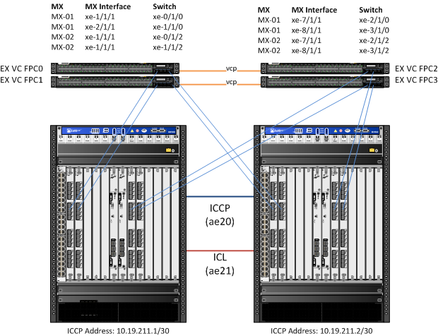
With that out of the way, consider diagram below. This is a simplified version of the topology that was reconfigured:
Since the MX’s were originally configured in a Virtual Chassis (VC) topology, the first objective is to prepare MX-02 to be separated from the chassis. I began this by first removing all but one of the VC ports from both MX’s using the following commands:
request virtual-chassis vc-port delete fpc-slot 2 pic-slot 0 port 0
request virtual-chassis vc-port delete fpc-slot 7 pic-slot 0 port 0
request virtual-chassis vc-port delete fpc-slot 8 pic-slot 0 port 0
The VC Ports will be used later to create the Inter-Chassis Link (ICL) later in the migration. This left xe-1/0/0 as the remaining VC Port. From there, all physical ports on MX-02 (currently configured as VC Member 1) are disabled using the commands below:
set interfaces ge-12/0/0 disable
<..snip..>
set interface xe-20/3/3 disable
This prevents MX-02 from forwarding traffic on the network – a key point in preparing for the migration. Once MX-02 was removed from the Virtual Chassis configuration and the MC-LAG is applied, the interfaces would become active and cause severe problems on the network. I created an apply-group to ensure that the interfaces would not come up until later:
groups {
     disable-interfaces {
         interfaces {
             <*> {
                 disable;
             }
         }
     }
 }
interfaces {
     apply-groups disable-interfaces;
}
With the interfaces disabled, I proceeded to remove the last MX-VC interface from both MX’s to sever the VC completely:
request virtual-chassis vc-port delete fpc-slot 1 pic-slot 0 port 0
Once the VC is severed I can now make changes to MX-02 without affecting the configuration on MX-01. I then loaded the MC-LAG configuration on MX-02 (similar to the LAG configuration show above) and committed the configuration. From there I deleted the VC configuration using the command below and rebooted MX-02:
request virtual-chassis member-id delete
Once MX-02 came back up, and upon confirming that the interfaces are still disabled, I began to stage the MC-LAG configuration and set the apply-group to disable all interfaces on MX-01. Once this was complete I deleted my apply-group on MX-02 to enable the interfaces, then committed the changes to both MX-01 and MX-02. At this point MX-02 became active on the network, and MX-01 is now inactive. From there I had to clear ARP on all the switches and hosts that were originally connected because of the change in the IRB’s MAC address, or simply wait for it to expire on hosts that I could not access. Lastly, I deleted the VC configuration and rebooted MX-01 using the command below:
request virtual-chassis member-id delete
From there, I removed the apply-groups configuration on MX-01 and confirmed the MC-LAG configuration and that traffic was flowing properly:
On MX-01:
root@MX-01> show iccp

Redundancy Group Information for peer 10.19.211.2
  TCP Connection       : Established
  Liveliness Detection : Up
  Redundancy Group ID          Status
    1                           Up

Client Application: lacpd
  Redundancy Group IDs Joined: 1

Client Application: l2ald_iccpd_client
  Redundancy Group IDs Joined: 1

root@MX-01> show interfaces mc-ae id 2
 Member Link                  : ae1
 Current State Machine's State: mcae active state
 Local Status                 : active
 Local State                  : up
 Peer Status                  : active
 Peer State                   : up
     Logical Interface        : ae1.0
     Topology Type            : bridge
     Local State              : up
     Peer State               : up
     Peer Ip/MCP/State        : 10.19.211.2 ae21.0 up
On MX-02:
root@MX-02> show iccp

Redundancy Group Information for peer 10.19.211.1
  TCP Connection       : Established
  Liveliness Detection : Up
  Redundancy Group ID          Status
    1                           Up

Client Application: lacpd
  Redundancy Group IDs Joined: 1

Client Application: l2ald_iccpd_client
  Redundancy Group IDs Joined: 1


root@MX-02> show interfaces mc-ae id 2
 Member Link                  : ae1
 Current State Machine's State: mcae active state
 Local Status                 : active
 Local State                  : up
 Peer Status                  : active
 Peer State                   : up
     Logical Interface        : ae1.0
     Topology Type            : bridge
     Local State              : up
     Peer State               : up
     Peer Ip/MCP/State        : 10.19.211.1 ae21.0 up
And that’s all she wrote! Please feel free to leave comments and questions below.

Really nice effort. Illustrated some how a complex topic in very simple way. Thanks..
Why did you feel the need to break the Virtual Chassis? Would managing one device not be easier then having to manage two?
The biggest driver to split the Virtual Chassis was stability of the network. While VC provides easier management, it has the disadvantage of being a single point of failure on the network. Between software bugs and hardware failures there are plenty of opportunities for a single failure to bring down the entire core of the network. MC-LAG allowed us to provide many of the benefits of VC (minimizing spanning tree on the network, active/active flow capabilities) while keeping each core switch independent from the other.
Hi Clay, agreed that VC will become a single point of failure in the network. And that’s the same what I am going to do next week, converting VC to MC-LAG.
Awesome! Let me know how it goes! And good luck with the split – I hope this post was helpful for you!
Just out of curiosity, have you had that many software bugs that caused problems when either upgrading or hardware failed (specifically on the MX series – since we have a pair of new MX104’s – I’m curious)? I would still consider the MC-LAG implementation itself as a single point of failure. If a bug exists on one unit, it will exist on the other. We have had this situation present itself on a SAN, where independent controllers in an active/passive configuration failed the active controller, so the passive controller became active, then the newly active controller crashed due to the same bug.
Hey Eric,
Good question! While I can’t get into all the details, we ran into 4 individual PR’s that affected the stability of the MX Virtual Chassis, and all were due to replication tasks failing for the VC, or the RE not handing the RE role to the backup switch. There was also one odd issue where the configuration failed to validate upon rebooting the RE. In an active/active MC-LAG both switches are actively forwarding traffic, and in those instances a hardware failure would only bring down one switch instead of the brains of of the entire VC. Bad traffic would certainly bring down both switches, but in our case it was due to partial hardware failures and buggy implementations of the VC. Moreover, while certainly not best practice we can run two separate JUNOS images on each MX to address those ‘bad traffic’ issues and/or fix problematic code. I hope that answers your question!
Thank you! Great information. We actually were recommended by Juniper to implement MC-LAG versus VC. Adding the VC license would have cost $36k+, but it sounds like it would have added instability, which obviously isn’t good. So, we have implemented MC-LAG this week and it is working perfectly. After thinking about how we can potentially have a different version of JUNOS on each router, test failures easier, have different routing tables (if necessary), and not have to deal with any VC fail-over issues, it simply made more sense to use MC-LAG. We could even replace the MX104’s with MX240’s with a similar configuration, one at a time, without downtime, whereas we couldn’t do this with a VC config. So far, we’re happy with the decision. Thanks for the reply!
it is great, while my customer has the identical requirement, and it is good reference materials for us. thanks a lot…
Really useful article. One question does MX104 support virtual chassis ?
Many Thanks
Brijesh
Hello
please can you elaborate
more on VC disadvantages ,and does any one faced these problems practically
Can I set same IP address on ae1 on MX01 and MX02. For example,
instead of
unit 0 {
family bridge {
interface-mode trunk;
vlan-id-list 1-4094;
set –>
unit 0 {
vlan-id 1000
family inet {
address AA.BB.CC.DD/30;
}
Is there any limitation of features when deploying MC-LAG vs Virtual Chassis?
Does the configuration between the 2 MC LAG peers need to be exactly identical?
In situation where you are dynamic routing protocols like OSPF, is it required to configure VRRP?
How are VRF’s handled in MC-LAG compared to the way it is handled in virtual chassis?
Can independent MC-LAG peers be composed of virtual chassis? If so how many members in the VC are supported?
Thank You